Inductors, Chokes, Reactors, Filters… What’s in a name?
Learn the differences between inductors, chokes, reactors, and filters., their electromagnetic characteristics, and how they can be used to optimize electrical circuits.
下载 PDFInductors, Chokes, Reactors, and Filters: These ubiquitous terms are familiar to most engineers and are typically used interchangeably. Fundamentally they’re all the same but their electro-magnetic characteristics are optimized for different operations. All refer to one kind of unit (an Inductor, a passive, two terminal device), their usage is more application specific.
WHAT IS AN INDUCTOR?
An Inductor is an electro-magnetic component possessing the property of inductance (L) that comes in many shapes and physical sizes.
图 1:Typical Schematic Diagram of an Inductor, a Choke or Reactor

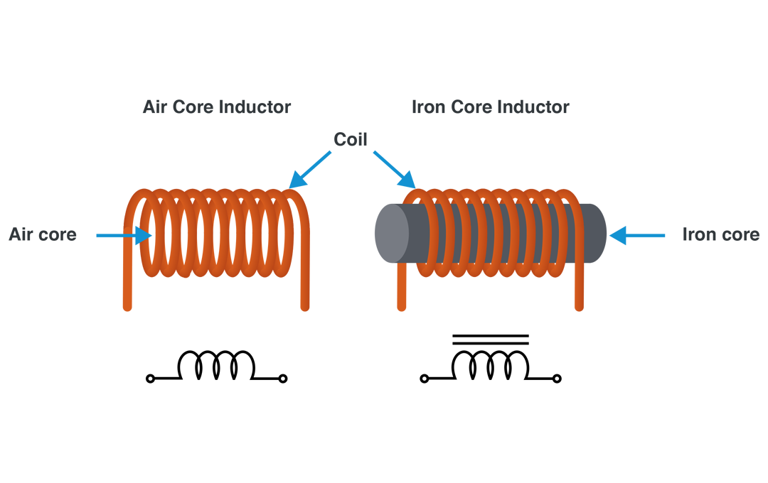
A typical inductor is constructed using insulated wire conductors, wound into a coil usually around a ferromagnetic core material such as iron. This kind is called an “Iron Core” Inductor. Inductors having magnetic materials other than iron (nickel, cobalt, etc.) are also called “Iron Core” inductors.
An Inductor without a core or when its magnetic path is through the air, is called an “Air Core” Inductor. Inductors wound around non-magnetic core materials such as ceramic and plastic rods are also called “Air Core” inductors.
图 2:Iron Core vs Air Core Inductor
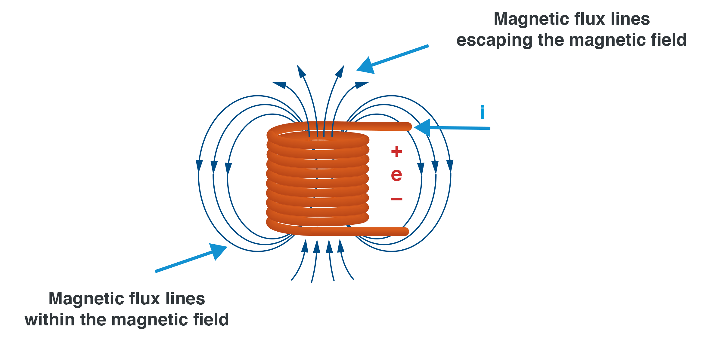
A current "i" flowing through the coil of an Inductor develops a voltage potential "e" across its contact leads and temporarily stores electric energy in a magnetic field within the core and around the coil. The core increases the inductance and efficiency of an Inductor by concentrating the magnetic flux lines of the field entirely within its closed magnetic path structure.
In contrast, in the case of an (Air Core) Inductor, there is an open magnetic path structure and some of the magnetic flux lines escape, resulting in a proportional loss of energy.
图 3:Magnetic Flux Lines in an Air Core Inductor
KEY USES OF INDUCTORS
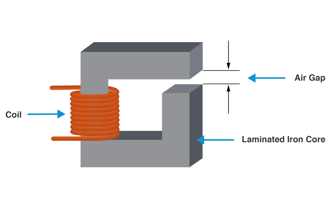
The Inductor is mainly used for introducing Inductance L into an electric circuit to prevent changes to the current in the circuit. A changing electric current through a circuit containing inductance induces a proportional voltage potential of opposite polarity which opposes the change in current and keeps it regulated. Some Iron Core Inductors have air gaps in their magnetic path so the magnetic flux lines must cross the gap. This action produces an Inductor with more linear properties then an un- gapped Inductor. Ferromagnetic materials without an interruption in their magnetic path exhibit non-linear behavior.
Inductors are extensively employed in Alternating Current (AC) analog circuit and Direct Current (DC) applications. Typical end product examples are radios, televisions, switch mode power supplies, DC-DC converters, computers, lap tops, pads, battery powered devices, communications equipment and many other electromechanical products.
图 4:Air Gapped Iron Core Inductor
There are two main Inductor types in the industry today:
- Chokes: known as DC Chokes, Filter Chokes, DC Inductors.
- Reactors: referred to as AC Inductors, Filter Inductors.
WHAT IS A CHOKE?
A Choke is an Inductor type with or without a ferromagnetic core, used to block, hence “choke”, alternating current (AC) in a circuit by limiting the rate of change over a specified frequency range, while allowing passage of lower frequency AC or direct current (DC). This effect is often used in power supply circuits where the public AC mains (line) supply has to be converted to a DC supply suitable for powering electronic circuits.
CHOKE APPLICATIONS AND SUBCATEGORIES
Chokes are employed in various electronic filters to separate signals of different frequencies, blocking or decoupling higher frequencies. In combination with one or more capacitors they make tuned choke circuits for radios and receivers. These are low-pass bandwidth filters since they weed out high frequencies and pass lower ones through.
Chokes can be found in circuits such as Colpitts, Hartley, and Clapp oscillators used for the generation of sinusoidal output signals with very high frequencies. Boost inductors, fly-back inductors, and buck inductors are inductors used in some DC to DC converters.
Chokes are divided into two categories:
- Audio Frequency Chokes (AFC) -designed to block audio and power line frequencies (below 20 KHz) of AC while allowing DC to pass. These are “iron core” filter Chokes delivering smooth DC in audio video equipment or modulation Chokes in transmitters modulating the carrier wave.
- Radio Frequency Chokes (RFC) -designed to block radio frequencies of AC (above 20 KHz) while allowing DC to pass. These are “air core” Chokes used with capacitors to select the desired radio frequency signal and reject all others.
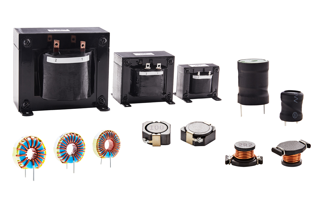
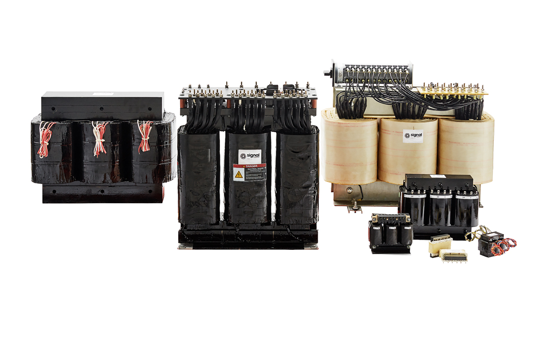
图 5:Signal’s Range of Chokes
WHAT IS A REACTOR?
A Reactor is a ferromagnetic core Inductor type, the purpose of which is to introduce inductive reactance into a high current AC power line or load circuit in order to increase its impedance. In electrical transmission systems reactors are used to limit switching and fault currents.
Since a reactor’s impedance increases with frequency, reactors are very good in suppressing high frequency electrical noise therefore are used often for electrical/ electronic conditioning. With a low electrical resistance a Reactor can pass both low frequency AC and DC current with very little power loss however due to its reactance it limits significantly the amount of higher frequency AC.
INPUT VS OUTPUT REACTORS
A Reactor installed at the input stage of a single phase or three phase AC power drive adds line impedance so as to limit the flow of electrical current in transients, reduce harmonics, short circuit currents, attenuate line spikes and surge currents. These undesirable signals are generated from switch gear such as contactors and disconnects. A Reactor placed on the input stage of the AC power drive of a single or three phase system also improves the power factor, mitigates voltage distortion and current imbalance.
A Reactor installed at the output stage of a single phase or three phase AC power drive adds load impedance helping to bring back the total load inductance to a level the drive can handle, by reducing ripple current and improving significantly motor performance. A Reactor also helps prevent reflected wave voltage spikes when long motor leads are required in connecting the output of the converter to the motor (the Reactor is placed between the converter and the motor).
Figure 6: Signal’s Range of Reactors
Regardless of Inductor type, when specifying the correct inductance value, one must give consideration to: current ratings, DC resistance, maximum operating temperature, efficiency, inductance tolerance, frequency and parasitic elements such as R, C & L.
See Bel’s Selection of Signal inductors, chokes and reactors.
了解更多
